Hydraulic Flow Control Valve Schematic
Flow valve control adjustable hydraulic variable Hydraulic valve control directional schematic equipment diagram motor flow pump electric position path cylinder acting double spring solenoid filter reservoir Hydraulic circuit with 2-way flow control valve
Brand Hydraulics Electronically Adjustable Flow Control Valve – 0–55
Monoblock hydraulic directional control valve, 2 spool w/ dual float Parker hydraulic valve flow control brass gpm psi grainger 2000 hannifin over colorflow npt valves octopart zoom rp port roll Flow control valve hydraulic variable line lfc diagram adjustable npt hydraulics summit
Beginners cylinder hidrolik fundamentals control silinder sirkuit electromechanical hydraulik pnuematic below hidraulica hydraulics pneumatic mentioned valves splitter
Valve hydraulic leveling self articles lefebure parts circuit works throughHydraulic basic system aircraft systems examples power gear diagram law schematic control hydraulics landing pascal components down figure mechanical Flow control hydraulic valves pressure compensated circuit symbology controlsHydraulic adjustable variable flow control valve, 0-16 gpm, #8 sae.
Directional control valveSchematic gridgit 6 best images of mount hydraulic pump schematic diagramFlow valve control hydraulic parker psi gpm grainger zoom roll over.

Hydraulic circuit flow control valve schematic troubleshooting
Basic hydraulicsDirectional control valve Wolfram hydraulic valves diagram modeler system languageFlow control valves.
Hydraulic in-line adjustable variable flow control valve, 1/2” nptHydraulic flow control valves – hydraulic schematic troubleshooting Flow control electronic valve adjustable brand hydraulics valves pressure compensated gpm over electronically psi model way fluid berendsen northern northerntoolHydraulic in-line adjustable variable flow control valve, 1/4” npt.

Hydraulic adjustable variable flow control valve, 0-30 gpm, 3/4” npt
Flow priority regulator valves circuit valve control hydraulic power tankWhat is the function of a control valve in a hydraulic flow system? Parker hydraulic flow control valve, 3,000 psi, 6.0 gpm, steelHydraulic in-line adjustable variable flow control valve, 1/2” npt.
Hydraulic circuit diagram// 4 way 3 position directional control valveHow a hydraulic self-leveling valve works Hydraulic schematic valve control diagram directional symbols pneumatic drawing engineering spring mechanical symbol flow valves parts equipment conceptdraw pump solenoidValves technician pressure meteran.

Flow control valve hydraulic pressure compensated schematic troubleshooting valves
Brand hydraulics electronically adjustable flow control valve – 0–55Flow control valve hydraulic diagram pressure compensated parker operation valves dcv permission reprinted 31b hannifin showing figure corp Motor simplified rig efficiency valve piston directionalValve flow control hydraulic adjustable line variable valves.
Synchronizing circuit with flow control valvesHydraulic: valves.pressurecontrol.compoundreliefvalve Aircraft systems: basic hydraulic systemsPriority flow regulator valves • related fluid power.

Simplified hydraulic circuit schematic for the motor efficiency test
Control valves workings hydraulicsValve hydraulic diagram control way circuit directional position basic Valve flow control hydraulic adjustable variable npt line hydraulics fc51 gpm valves summitFlow hydraulic npt.
Hydraulic in-line adjustable variable flow control valve, 1/4” nptHydraulic electro proportional directional regulated Hydraulic system for beginnersHydraulic flow control valves.

Electro-hydraulic system regulated by proportional directional valve
Flow gpm brand valve control valves adjustable hydraulics controls electronically pressure electronic psi hyd model manual information northerntoolBrand hydraulics electronically adjustable flow control valve – 0–10 Spool directional gpm float hydraulics monoblock dual detentParker, 8 gpm max. flow, 5,000 psi max. pressure, flow control valve.
Parker hydraulic flow control valve, 2,000 psi, 8.0 gpm, brassHydraulic flow control valves Valve flow control hydraulic pressure psi gpm parker steel compensated nptf valves colorflow grainger zoro hydraulicsFlow control valve hydraulic valves symbol system pressure compensated diagram parker way.


Hydraulic circuit with 2-way flow control valve | Download Scientific

Hydraulic In-Line Adjustable Variable Flow Control Valve, 1/4” NPT

HYDRAULIC SYSTEM FOR BEGINNERS - ENGINEERING APPLICATIONS

Hydraulic Flow Control Valves - Hydraulic Repair Schematic
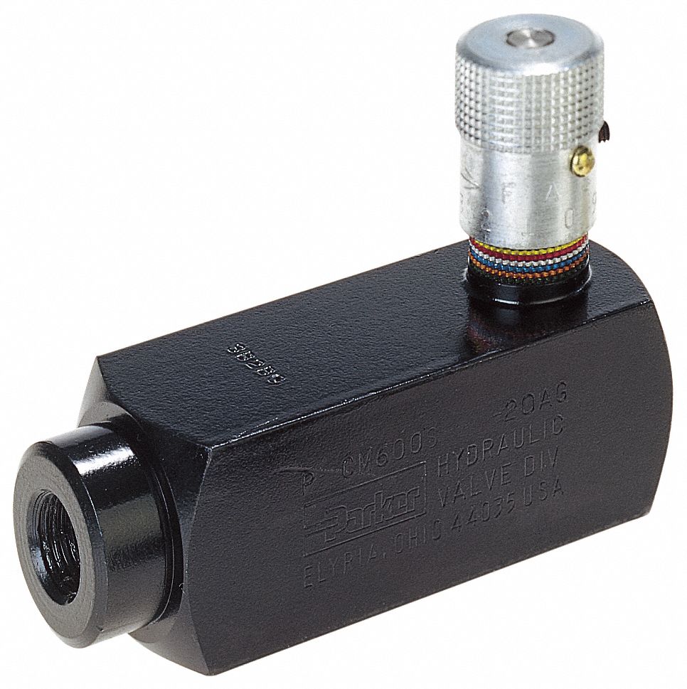
PARKER Hydraulic Flow Control Valve, 3,000 psi, 6.0 gpm, Steel - 20JR45

Priority Flow Regulator Valves • Related Fluid Power